
 English
  中文简体
中文简体
Content
- 1 What Is Electrolyzer Electrode Felt?
- 2 Types of Electrode Felt Used in Electrolyzers
- 3 Key Performance Parameters of Electrode Felt for Electrolyzers
- 4 Electrode Felt in PEM Water Electrolyzers
- 5 Carbon and Graphite Felt for Alkaline Electrolyzers and Flow Batteries
- 6 Surface Treatment and Functionalization of Electrode Felt
- 7 Selecting Electrode Felt for Your Electrolyzer: Practical Considerations
What Is Electrolyzer Electrode Felt?
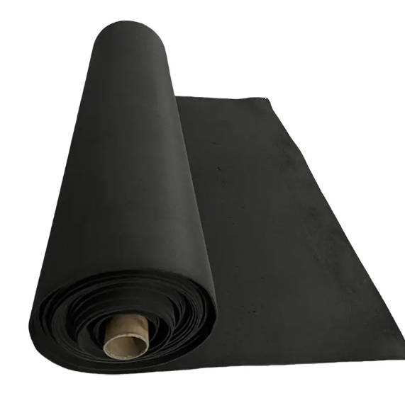
Electrolyzer electrode felt is a porous, fibrous material used as the electrode substrate or gas diffusion layer (GDL) in electrochemical cells — most commonly in water electrolyzers for hydrogen production, redox flow batteries, and fuel cells. The felt structure provides a three-dimensional network of conductive fibers that simultaneously serves as an electron conductor, a reaction surface for electrochemical processes, and a porous medium through which reactants and products (gases and electrolyte) can transport in and out of the active zone.
Unlike flat plate or mesh electrodes, felt electrodes maximize the active surface area available for electrochemical reactions within a compact volume. A single cubic centimeter of high-quality electrode felt can present a geometric surface area of 0.5 to 2.0 m² depending on fiber diameter, porosity, and felt thickness — a critical advantage in systems where reaction rate and current density are limited by available electrode area.
Electrode felt is available in several base materials, each suited to different electrochemical environments, operating temperatures, and electrolyte chemistries. The selection of the correct felt grade is one of the most consequential material decisions in electrolyzer stack design, directly influencing efficiency, durability, and operating cost over the system's service life.
Types of Electrode Felt Used in Electrolyzers
The three primary material families for electrolyzer electrode felt are carbon/graphite felt, metal felt (titanium and nickel), and composite variants. Each offers a distinct combination of electrochemical performance, chemical stability, and mechanical properties that determines its suitability for specific electrolyzer technologies.
| Felt Type | Base Material | Key Properties | Primary Application |
|---|---|---|---|
| Carbon felt | PAN or rayon-derived carbon fiber | Good conductivity, low cost, acid-stable | Redox flow batteries, alkaline electrolyzers |
| Graphite felt | Heat-treated carbon felt | Higher conductivity, improved oxidation resistance | Vanadium redox flow batteries, high-current cells |
| Titanium felt | Sintered or woven Ti fiber | Corrosion-resistant in acid, dimensionally stable | PEM electrolyzers (anode side) |
| Nickel felt | Sintered nickel fiber | Alkaline-stable, high surface area, catalytic activity | Alkaline and AEM electrolyzers |
The choice between these material families is largely determined by the electrolyte environment. Proton exchange membrane (PEM) electrolyzers operate under strongly acidic conditions (pH 0 to 2) and high differential pressures, which eliminates carbon felts on the anode side — where oxidizing potentials accelerate carbon corrosion — and mandates titanium felt for its passive oxide layer stability. Alkaline electrolyzers operate in concentrated KOH (25 to 35 wt%), where nickel felt is chemically compatible and cost-effective. Carbon and graphite felts find their primary electrolyzer application in flow battery systems and alkaline cells where lower oxidizing potentials allow carbon to survive extended operation.
Key Performance Parameters of Electrode Felt for Electrolyzers
Specifying electrode felt for electrolyzer applications requires understanding how structural and material properties translate into electrochemical performance. The parameters below are the most consequential in stack design and component selection:
- Porosity (%): The void fraction of the felt determines how easily gases and liquids transport through the structure. Electrode felts for electrolyzers typically operate in the 70 to 90% porosity range. Higher porosity reduces mass transport resistance but also reduces the fiber contact area available for current collection. Optimizing porosity is a balance between ionic and electronic transport.
- Through-plane and in-plane electrical resistivity: Current must flow from the bipolar plate through the felt to the membrane interface with minimum ohmic loss. Through-plane resistivity of 10 to 100 mΩ·cm is typical for high-quality electrode felts. Resistivity increases under compression, making compression uniformity across the stack critical to consistent performance.
- Fiber diameter and felt thickness: Finer fibers increase surface area and improve reaction kinetics but reduce mechanical strength. Felt thickness (typically 1 to 5 mm for electrolyzer applications) must be sufficient to distribute compression without fully collapsing the pore network, and thin enough to minimize the distance reactants must diffuse to reach the active membrane surface.
- Wettability and contact angle: In liquid-fed electrolyzers, the felt must be sufficiently hydrophilic to allow electrolyte penetration into the pore structure while enabling gas bubble detachment and removal. Surface treatment — including heat treatment, acid washing, or hydrophilic coating — modifies the native wettability of both carbon and metal felts to optimize two-phase flow behavior.
- Compressive behavior: Electrode felt is compressed between the bipolar plate and membrane during stack assembly. The felt must maintain adequate porosity and electrical contact across the required compression range (typically 20 to 40% strain) without permanent deformation that would alter cell geometry over thousands of operating hours.
Electrode Felt in PEM Water Electrolyzers
PEM water electrolyzers represent the fastest-growing application for high-performance electrode felt, driven by the global expansion of green hydrogen production capacity. In a PEM electrolyzer cell, the electrode felt functions as the porous transport layer (PTL) — positioned between the bipolar plate and the catalyst-coated membrane — and must simultaneously conduct current, transport water to the membrane, and remove oxygen (anode) or hydrogen (cathode) from the reaction zone.
On the anode side, titanium felt is the standard choice. The oxygen evolution reaction (OER) at the anode generates strongly oxidizing conditions at potentials of 1.8 to 2.2 V vs. SHE — a regime that rapidly corrodes carbon fiber and passivates many metals. Titanium forms a stable TiO₂ passive layer that resists this oxidation while maintaining acceptable electronic conductivity. To further reduce interfacial contact resistance, anode-side titanium felts are commonly coated with platinum group metal (PGM) coatings — platinum or iridium oxide — at thicknesses of 0.1 to 1.0 μm.
On the cathode side, where hydrogen evolution occurs at reducing potentials, carbon felt or sintered titanium felt are both viable. Carbon felt is lower cost and performs adequately in the reducing cathode environment; titanium felt is used where higher pressure operation or long-term dimensional stability under compression cycling is required. Cathode-side felts may also receive platinum or carbon-based catalytic coatings to reduce hydrogen evolution overpotential.
Stack efficiency in PEM electrolyzers is directly sensitive to PTL quality. Research consistently shows that optimizing titanium felt porosity, fiber diameter, and surface coating can reduce cell voltage by 50 to 150 mV at practical current densities (1 to 3 A/cm²) — translating directly into lower electrical energy consumption per kilogram of hydrogen produced.
Carbon and Graphite Felt for Alkaline Electrolyzers and Flow Batteries
Carbon and graphite electrode felts remain the dominant choice in two major electrochemical applications: alkaline water electrolysis and vanadium redox flow batteries (VRFB). In both cases, the combination of high porosity, good electronic conductivity, chemical stability in the operating environment, and relatively low cost make carbon-based felts the practical engineering choice.
In alkaline electrolyzers, carbon felt is used primarily on the cathode side for hydrogen evolution, where the reducing environment prevents the oxidative degradation that occurs at the anode. The felt is typically pre-treated — either by heat treatment in inert atmosphere to graphitize surface carbon, or by acid treatment to remove surface impurities and increase hydrophilicity — before assembly into the cell stack.
In vanadium redox flow batteries, graphite felt electrodes undergo electrochemical reactions at both positive and negative electrodes during charge and discharge cycles. The felt must maintain consistent electrochemical activity across hundreds of thousands of cycles. Surface activation — by heat treatment at 400°C in air, acid treatment with H₂SO₄/HNO₃, or electrochemical oxidation — creates oxygen-containing functional groups on the fiber surface that significantly improve vanadium ion reaction kinetics and electrolyte wettability. Activated graphite felt in a VRFB can deliver charge-discharge efficiencies exceeding 80% coulombic efficiency at practical current densities, with performance directly tied to the quality and consistency of the felt substrate.
The key distinction between carbon felt and graphite felt lies in the degree of graphitization. Standard carbon felt is produced by carbonizing polyacrylonitrile (PAN) or rayon precursor fibers at temperatures of 1,000 to 1,500°C, yielding a partially ordered carbon structure. Graphite felt is produced by further heat treatment at 2,000 to 3,000°C, which converts the amorphous carbon regions to a more ordered graphitic structure — improving electrical conductivity by a factor of 2 to 5, reducing surface oxygen content, and enhancing chemical stability under oxidizing potentials.
Surface Treatment and Functionalization of Electrode Felt
Raw electrode felt — whether carbon, graphite, titanium, or nickel — rarely delivers optimal electrochemical performance without surface treatment. The as-received fiber surface may be hydrophobic, contaminated with sizing agents or oxide layers, or lacking the functional groups necessary to catalyze the target electrochemical reaction efficiently. Surface treatment is therefore a standard step in electrode felt preparation for electrolyzer and flow battery applications.
Common treatment methods include:
- Thermal oxidation: Heating carbon or graphite felt in air at 350 to 500°C for 30 to 120 minutes introduces hydroxyl, carbonyl, and carboxyl groups on the fiber surface. These oxygen-containing groups enhance wettability and improve reaction kinetics for vanadium and other redox couples. Temperature and duration must be controlled precisely — excessive treatment burns away fiber material and reduces felt strength and conductivity.
- Acid treatment: Immersion in concentrated H₂SO₄, HNO₃, or mixed acid solutions etches the fiber surface, removes contaminants, and introduces surface functional groups. Nitric acid treatment is particularly effective for increasing surface oxygen content and improving hydrophilicity. Acid-treated felt is rinsed thoroughly and dried before use.
- Catalyst coating: For PEM electrolyzer PTLs, PGM catalyst coatings (Pt, IrO₂) are applied by physical vapor deposition, electrodeposition, or wet chemical methods to reduce contact resistance and improve reaction kinetics at the felt-membrane interface. Coating uniformity across the three-dimensional felt structure is a key quality parameter, as uncoated regions create high-resistance zones that reduce local current density and generate heat.
- Hydrophobic treatment: In some gas diffusion applications, PTFE (polytetrafluoroethylene) is applied to carbon felt to create a mixed wettability structure — hydrophilic fiber surfaces for electrolyte contact with hydrophobic zones that promote gas bubble detachment and transport. PTFE loading of 5 to 30 wt% is typical, applied by dip coating followed by sintering at 350°C.
Selecting Electrode Felt for Your Electrolyzer: Practical Considerations
Procurement and engineering decisions around electrode felt involve balancing electrochemical performance requirements against cost, availability, and compatibility with the broader stack design. The following framework covers the critical decision points:
- Define the electrolyzer technology and electrolyte: PEM (acidic, high pressure) → titanium felt anode, carbon or Ti felt cathode. Alkaline (KOH, 60–80°C) → nickel felt or carbon felt. AEM (alkaline membrane) → nickel or carbon felt. VRFB → graphite felt, both electrodes.
- Specify porosity and thickness based on current density targets: Higher target current densities (above 2 A/cm²) require optimized mass transport — favor higher porosity felt with finer fiber diameter and thinner cross-section to minimize diffusion path length.
- Confirm chemical compatibility with operating conditions: Verify felt material stability across the full range of operating potential, temperature, electrolyte concentration, and any transient conditions (startup, shutdown, reversal) the cell may experience.
- Evaluate compression behavior against stack design: Request stress-strain data and confirm that the felt's compressive response at the specified assembly torque produces the target contact resistance and residual porosity. Felts that are too stiff prevent uniform compression; felts that are too compliant may over-compress and block pore networks.
- Assess surface treatment requirements: Determine whether the supplied felt requires additional activation, cleaning, or coating before stack assembly. Some suppliers provide pre-treated felt; others supply as-produced material requiring in-house preparation.
As green hydrogen production scales globally, electrode felt quality has become an increasingly critical performance and cost lever. Advances in fiber processing, surface functionalization, and coating technology continue to push the performance boundaries of both metal and carbon felt substrates — making material selection an active engineering discipline rather than a commodity procurement decision.


