


 English
 中文简体
Content
- 1 What Electrode Felt Does Inside a Flow Battery
- 2 Five Electrode Felt Quality Parameters That Decide Cell Efficiency
- 3 PAN-Based vs Viscose-Based Electrode Felt: Which One Fits Your Stack
- 4 How Felt Quality Moves Voltage Efficiency: The Data
- 5 Sourcing Checklist for Electrode Felt
- 6 Frequently Asked Questions About Electrode Felt
At a vanadium redox flow battery (VRFB) integrator, two 3.0 mm electrode felt samples once arrived from different suppliers with nearly identical datasheets: 92% porosity, 3.0 mm thickness, and the same bulk density. In side-by-side single-cell tests at 160 mA/cm2, one cell held 79.1% voltage efficiency while the other dropped to 70.4%. The 8.7-point gap did not come from the electrolyte or the bipolar plates; it came from the felt's precursor fiber, graphitization degree, area-specific resistance, and surface oxygen content. Those four parameters define where electrode felt quality is won or lost.
What Electrode Felt Does Inside a Flow Battery
Electrode felt is the working surface of a flow battery electrode. This porous carbon fiber mat supplies the reaction sites, distributes the electrolyte, and carries current to the bipolar plate. In a VRFB, every vanadium ion that stores or releases energy must reach a carbon fiber surface to do so.
Electrode felt is a porous, electrically conductive mat of carbonized or graphitized fibers that serves as the reaction electrode for redox couples in vanadium and zinc-bromine flow batteries.
The fiber network must satisfy three contradictory demands at once: thin, densely packed fibers maximize reaction surface area; large, open pores minimize pumping losses; and a highly graphitized structure keeps ohmic resistance low. Because all three shift under compression, in-cell behavior matters more than free-standing thickness. In a standard VRFB architecture, felt with 3.0–4.6 mm free thickness is compressed to 70–80% of that value against the flow field, which produces the electrical contact and the sealing gap the cell was designed around.
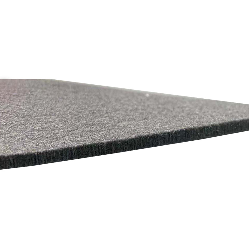 CVD-Coated Electrode Felt for Flow Battery ElectrodesThis electrode felt features gas-phase deposited carbon nanotubes for high surface area and permanent hydrophilicity, with grafted structures that suppress hydrogen evolution, making it suitable for various flow battery electrode applications.View Product →
Because compressed thickness, not free thickness, sets the final cell gap, a felt that cannot hold dimensional tolerance shows up as uneven torque, leaking cells, and hot spots in the stack.
Five Electrode Felt Quality Parameters That Decide Cell Efficiency
Five measurable felt properties determine most of the efficiency difference between a marginal and a high-performing flow battery stack: area-specific resistance, porosity, fiber diameter, compression response, and surface oxygen content.
| Parameter | Typical operating range | Impact on stack performance |
| Area-specific resistance (ASR) | 0.5–5.0 ohm-cm2 under compression | Direct ohmic loss; every 1 ohm-cm2 of added resistance costs roughly 1–2 voltage-efficiency points at 160 mA/cm2 |
| Porosity | 85–95% | Higher porosity eases electrolyte flow and reduces pump loss but lowers fiber density per volume |
| Fiber diameter | 8–20 micron | Smaller fibers add reaction surface but are more fragile and easier to crush during stack assembly |
| Compression response | 20–40% deflection at 2–5 N/cm2 | Sets contact resistance and the sealing force window for the whole stack |
| Surface O/C ratio | 0.03–0.15 | Catalyzes vanadium redox reactions; a low ratio means slower kinetics and lower voltage efficiency |
< 3.0 ohm-cm2Recommended ASR ceiling for a high-efficiency VRFB electrode under stack compression
3.0 mmMost common compressed felt thickness in 10–100 kW vanadium flow battery stacks
0.10 O/CSurface oxygen-to-carbon ratio target for thermally activated electrode felt
The hidden variable is the oxygen-to-carbon ratio on the fiber surface. Two felts with identical geometry can differ by more than 300% in charge-transfer resistance purely because of surface chemistry.
PAN-Based vs Viscose-Based Electrode Felt: Which One Fits Your Stack
Choose PAN-based electrode felt when you need the lowest electrical resistivity and the highest graphitization degree. Choose viscose-based felt when you need a softer, more compressible electrode that conforms to curved or flexible flow fields.
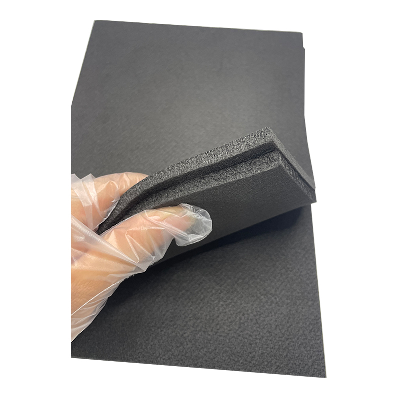 PAN-Based Graphite Felt with High Conductivity and PurityProduced via high-temperature graphitization at 2200°C, this felt offers low electrical resistivity, high oxidation resistance, and thermal stability up to 3200°C, ideal for demanding cell architectures requiring precise conductivity.View Product →
PAN-based felt
- Higher carbon yield and stronger individual fibers
- Lower area-specific resistance after graphitization above 2000 °C
- Dominant material in commercial VRFB electrodes
- Becomes more brittle as heat-treatment temperature rises
Viscose-based felt
- Softer, more flexible, easier to drape over complex geometries
- Widely used in thermal insulation and compressible cell designs
- Higher electrical resistivity than PAN after equivalent treatment
- Useful in zinc-bromine cells where conformability matters
 Viscose-Based Graphite Felt for Insulation and Ablation ResistanceMade from viscose rayon, this low-density felt provides excellent thermal insulation and ablation resistance, suited for high-temperature furnaces and applications where minimal thermal conductivity is essential.View Product →
Both precursor routes are available from Jiaxing Naco New Material Co., Ltd., a custom conductive carbon products factory that supplies PAN-based and viscose-based electrode felt in tailored thickness, density, and activation level. Matching the precursor to the cell architecture is the first step of felt specification, not a compatibility afterthought.
For a VRFB stack rated at 250 kW, a felt with 30% lower area-specific resistance can add roughly 1.5 percentage points to round-trip efficiency, a measurable reduction in levelized storage cost over 20 years of daily cycling.
How Felt Quality Moves Voltage Efficiency: The Data
Thermally activated, low-ASR electrode felt shifts the usable operating window of a VRFB stack upward by 30–50% for the same voltage-efficiency ceiling. The gap between activated and as-received felt starts small at low current density and widens steadily as current increases.
Thermal activation in air at 400–500 °C grafts hydroxyl, carbonyl, and carboxyl groups onto the fiber surface. These groups accelerate the V2+/V3+ and VO2+/VO2+ reactions by lowering the activation energy of electron transfer, which cuts charge-transfer resistance. This is the mechanism behind electrode surface chemistry controlling VRFB power density.
Surface activation is a process step, not a grade name. Ask for the O/C ratio and activation temperature, then verify ASR with a four-point probe at your own stack compression.
Sourcing Checklist for Electrode Felt
A complete electrode felt specification sheet includes measured ASR at operating compression, thickness tolerance, porosity, fiber diameter distribution, and O/C ratio. Without all five values on a batch certificate, a felt is unqualified regardless of price.
ASR under compression. Require resistance data measured at the same clamping force used in your stack, ideally 2–5 N/cm2, not at zero compression.
Thickness tolerance. Specify plus or minus 0.15 mm for a 3.0 mm felt; wider tolerances change the cell gap and contact resistance.
Fiber diameter distribution. Request SEM images with the full distribution, not just a single average value.
Batch consistency. Verify resistivity across rolls with a batch certificate; variation between batches is a common source of stack performance drift.
Activation status. Confirm whether the felt was thermally activated and what surface O/C ratio was achieved.
Wettability. A drop of electrolyte should wet the felt surface within seconds; slow wetting indicates an inactive or contaminated surface.
The most expensive mistake in felt procurement is optimizing price per square meter. Optimize the cost per percentage point of voltage efficiency instead, and the material becomes a minor line item in the stack budget.
Frequently Asked Questions About Electrode Felt
What is the difference between carbon felt and graphite felt?
Carbon felt is heat-treated at roughly 1000–1500 °C, while graphite felt is graphitized above 2000 °C. Graphitization increases electrical conductivity, thermal stability, and corrosion resistance. For flow battery electrodes, graphite felt is the standard because its lower resistance reduces ohmic losses in the cell.
What thickness of electrode felt is best for a vanadium flow battery?
Most VRFB stacks use 3.0–4.6 mm felt before compression, compressed to 70–80% of its free thickness in the cell. Thicker felt provides more active volume for vanadium ions but increases hydraulic resistance and pump energy. The right value depends on the flow field design and the target current density.
Why is thermal activation of electrode felt necessary?
Thermal activation in air at 400–500 °C adds oxygen functional groups that catalyze vanadium redox reactions. The result is a sharp reduction in charge-transfer resistance, which increases voltage efficiency, especially above 100 mA/cm2. As-received felt can lose 5–12 voltage-efficiency points at high current density.
Can electrode felt be reused in a flow battery after disassembly?
Graphite felt can be cleaned and reused if the fibers are not mechanically crushed and the felt is free of metal plating or irreversible deposits. Long operation changes the pore structure through compression set, so re-use requires re-measuring ASR, thickness, and porosity before the felt performs predictably.