


 English
 中文简体
Content
- 1 What CVD Treatment Actually Changes in Electrode Felt
- 2 Five Specifications to Demand from Any CVD Electrode Felt Manufacturer
- 3 Process Control: The Real Difference Between CVD Electrode Felt Manufacturers
- 4 VRFB, Zinc-Bromine and Beyond: Matching Felt Specification to Chemistry
- 5 What a Serious RFQ to a CVD Electrode Felt Manufacturer Should Contain
- 6 Frequently Asked Questions About CVD Electrode Felt Supply
Vanadium redox flow battery engineers rarely start with the electrode felt when they tune stack performance — until they measure half-cell overpotential. In VRFB stack testing, electrode overpotential is frequently the largest non-ohmic contributor to voltage loss, and one of the fastest corrections is a felt with a higher reactive surface area. That is why CVD (chemical vapor deposition) electrode felt has moved from an optional upgrade to a baseline specification in high-current-density stacks. Choosing a CVD electrode felt manufacturer is therefore a technical decision as much as a procurement one: the deposition process decides whether fibres carry a uniform, corrosion-resistant carbon layer or a decorative coating that fails under polarization.
What CVD Treatment Actually Changes in Electrode Felt
CVD electrode felt is a carbon or graphite felt in which a pyrolytic carbon layer is deposited directly onto fibre surfaces from a gas phase, raising the electrochemically active surface area while preserving the open porous network.
The base material is usually a PAN-based carbon felt, or a graphite felt produced from the same precursor after a graphitization step above 2000 °C. The felt moves through a low-pressure furnace while a carbon-source gas — commonly methane or propane — flows across and through the thickness. At deposition temperatures around 800–1100 °C, the gas decomposes on the heated fibres and leaves behind solid carbon. Each individual fibre gains a rough, nodular coating, and the effective surface area climbs well beyond the geometric fibre surface.
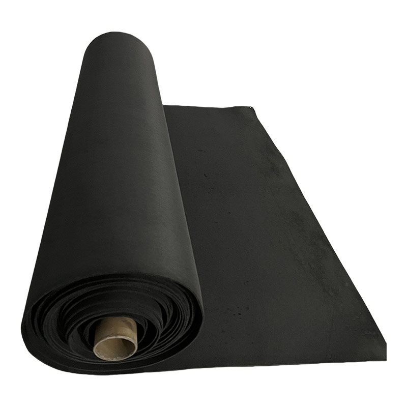
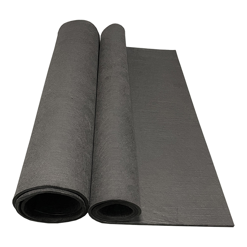 PAN-Based Carbon Felt for High-Temperature Electrode SubstratesThis felt is produced from needled PAN precursor carbonized at 1200°C, offering high temperature resistance, chemical inertness, and suitable thermal conductivity. It is the base material for CVD coating and electrode applications discussed in this section.View Product →
What changes in measurable terms:
- Active surface area: standard CVD treatments lift specific surface area into the 0.5–1.5 m²/g range; nano-structured deposition targets 2 m²/g and above.
- Through-plane resistivity: the coating bridges surface defects on fibres and typically brings resistivity into the 3–10 Ω·cm band.
- Corrosion resistance: a dense pyrocarbon layer shields the substrate from oxidizing electrolytes, particularly charged vanadium(V) solution.
- Porosity: the fibre network keeps 85–95% open volume, so electrolyte flow and pressure drop stay within design limits.
Five Specifications to Demand from Any CVD Electrode Felt Manufacturer
A competent CVD electrode felt manufacturer must quote thickness, resistivity, porosity, deposition weight gain and surface area as numbers with batch tolerances — not as marketing ranges.
These five values decide how a felt behaves in a real cell. Thickness defines compression; resistivity defines ohmic losses; porosity defines electrolyte flow; weight gain defines how much carbon was actually added; surface area defines activation overpotential.
| Specification | Typical range | Impact on cell performance |
| Felt thickness | 2.0–6.0 mm; batch tolerance ±0.2 mm | Sets compression ratio, contact resistance and stack pressure drop |
| Through-plane resistivity | 3–10 Ω·cm | Direct ohmic loss at rated current density |
| Porosity | 85–95% | Controls electrolyte permeability and hydraulic resistance |
| CVD weight gain | 1–5 wt% of total felt mass | Confirms actual carbon deposition; low values give minimal effect |
| Specific surface area | 0.5–1.5 m²/g; 2+ m²/g nano | Lowers activation overpotential on charge and discharge |
±0.2 mmthickness batch tolerance
3–10 Ω·cmtypical through-plane resistivity
85–95%open porosity window
<10%coefficient of variation across batches
Specific surface area by CVD route (m²/g)
Untreated
0.3
Standard CVD
1.2
Nano-structured CVD
2.4
The gap between the second and third row is where process development time is spent. For most VRFB stack builders, a well-run standard CVD coating delivers most of the benefit at a lower price than a nano-structured route.
Process Control: The Real Difference Between CVD Electrode Felt Manufacturers
Cross-sectional deposition uniformity, not surface appearance, is the first indicator of whether a CVD electrode felt manufacturer controls its process.
Electrode felt is commonly 3–6 mm thick, and the deposition gas has to reach the centre of the sheet while the furnace maintains a uniform temperature field across the full width. A rushed process deposits a dense pyrocarbon skin on the outer faces and leaves the core nearly untreated. The sheet looks coated, feels stiff and fails under load — the classic failure mode of low-cost CVD felt.
Four verification steps separate a controlled process from a label:
- Request cross-section SEM images that show coated fibres from the surface to the centre of the felt.
- Ask for weight gain per unit area in grams per square metre, including the spread across the batch.
- Insist on through-plane resistivity data, not a surface contact measurement.
- Confirm whether the substrate was graphitized; VRFB service requires graphitized fibre for corrosion resistance.
A factory that produces its own electrode felt can supply this documentation as part of the standard technical package rather than as a special request.
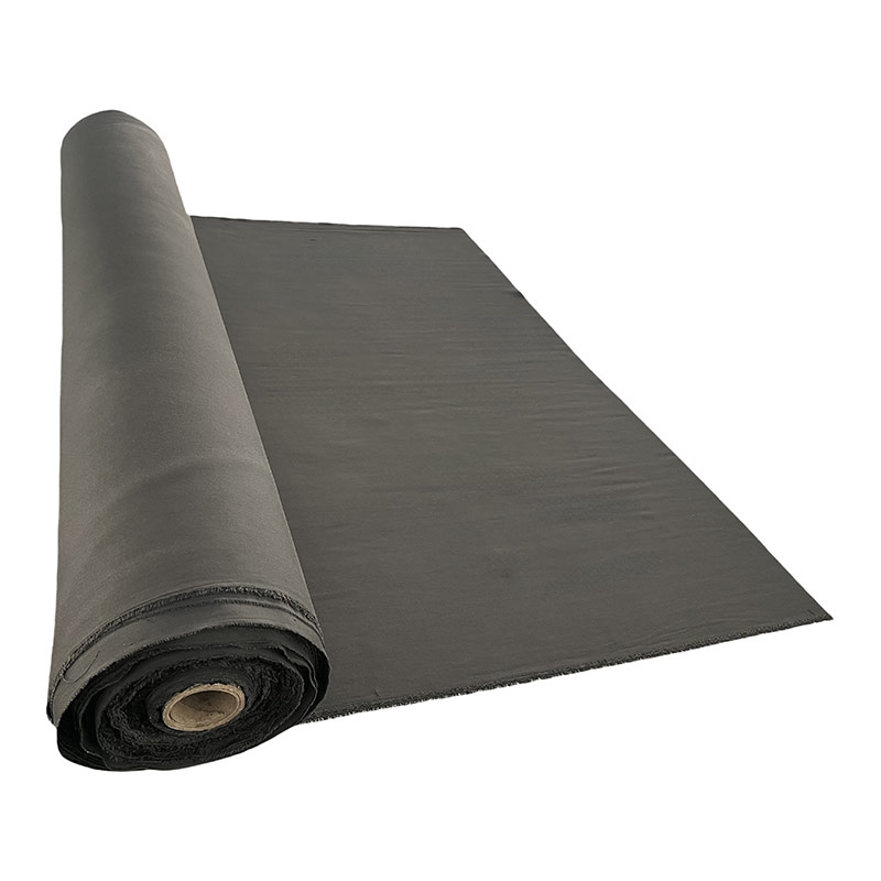
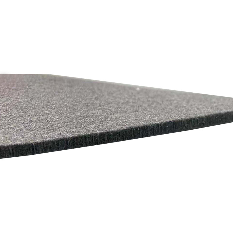 CVD-Coated Electrode Felt for Flow Battery ElectrodesThis gas-phase deposition electrode felt features up to 100 m²/g specific surface area, permanent hydrophilicity, and grafted structures that inhibit hydrogen evolution, making it suitable for vanadium and zinc-bromine flow battery systems requiring corrosion resistance.View Product →
VRFB, Zinc-Bromine and Beyond: Matching Felt Specification to Chemistry
Vanadium redox flow batteries need corrosion-resistant graphitized felt with a continuous CVD coating; zinc-bromine systems need a mechanically robust surface that distributes current without promoting dendrites.
The vanadium(V) ion in a charged electrolyte is strongly oxidizing. Exposed graphite surfaces degrade over cycling, and the failure shows up as rising charge-transfer resistance. A graphitized PAN-based felt with a complete, dense CVD carbon layer resists that attack, and the oxygen-containing groups on the coating — tunable during deposition or a post-treatment — improve reaction kinetics. The relationship between electrode surface chemistry and VRFB power density is the deciding factor in stack-level efficiency.
Zinc-bromine cells plate and strip zinc on the electrode during every cycle. Uneven current distribution produces dendrites and eventually shorts. A moderate CVD loading roughens the fibres just enough to spread current uniformly while keeping the felt flexible enough to survive compression. The dependence of this behaviour on electrode felt quality in zinc-bromine flow batteries is covered in our dedicated analysis.
VRFB electrode priorities
- Complete, dense CVD coating for oxidation resistance
- Graphitized PAN substrate
- Controlled oxygen functional groups
- High surface area for current-density targets
Zinc-bromine electrode priorities
- Moderate CVD loading to preserve flexibility
- Uniform current distribution
- Dendrite suppression at the fibre surface
- Consistent through-plane resistivity
What a Serious RFQ to a CVD Electrode Felt Manufacturer Should Contain
A serious RFQ lists your stack operating conditions, dimensional tolerances and batch statistics requirements — not just a unit price.
Jiaxing Naco New Material Co., Ltd., the custom conductive carbon products factory behind nacocarbonfiber.com, is a useful reference for this workflow: it controls the carbon felt substrate, the graphitization step and the electrode finishing processes in-house. Buying from a factory that owns the full chain shortens the feedback loop when a specification has to change after first cell testing.
- Felt thickness, and the compression ratio your stack frame applies to it.
- Through-plane and in-plane resistivity targets with acceptable tolerances.
- Porosity window, or a pressure-drop limit from your flow-field design.
- Target CVD weight gain or surface area; state explicitly if you need nano-structured deposition.
- Sample sheet size and quantity for in-cell validation before production volume.
- Coefficient-of-variation data from the last three production batches for thickness and resistivity.
For VRFB service, confirm the substrate grade; PAN-based graphite felt is the conventional base for CVD coating.
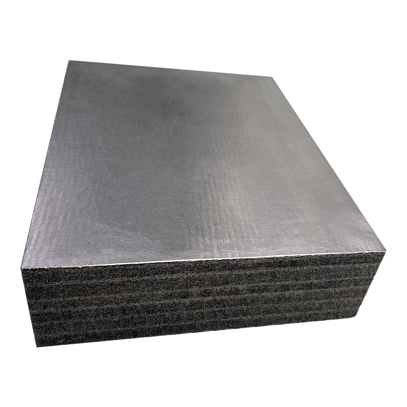
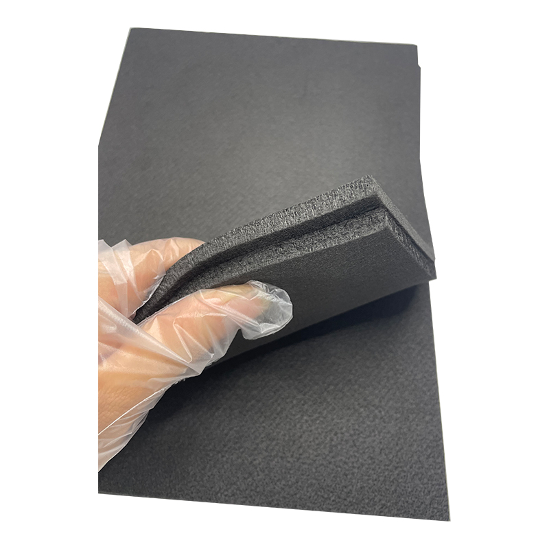 Graphitized PAN Felt for Oxidation-Resistant Electrode UseGraphitized at 2200°C, this PAN-based felt provides enhanced electrical and thermal conductivity, high oxidation resistance, and low thermal expansion. It serves as the conventional substrate for CVD coatings in VRFB electrodes, supporting durability in oxidizing electrolytes.View Product →
Frequently Asked Questions About CVD Electrode Felt Supply
What is the difference between CVD electrode felt and untreated carbon felt?
Untreated carbon felt has smooth fibres and a limited active area. CVD electrode felt carries a pyrolytic carbon layer that raises the active surface area, lowers through-plane resistivity and protects the fibres from oxidizing electrolytes — while keeping the porous structure that carries electrolyte flow.
Does CVD treatment make electrode felt brittle?
Heavy deposition embrittles the fibres, which is why weight gain is specified as a window rather than a maximum. A controlled coating in the 1–5 wt% range keeps the felt compressible and handleable; excessive deposition produces a crusted material that can crack when compressed inside a cell frame.
Can CVD electrode felt be produced to custom dimensions and properties?
Yes. Factory-based manufacturers such as Jiaxing Naco New Material Co., Ltd. supply sheets, rolls and die-cut parts. Substrate density, graphitization level and CVD deposition parameters can be adjusted against your operating current density, electrolyte chemistry and cell geometry.
What data should a buyer request before the first order?
Request a technical data sheet with thickness tolerance, through-plane resistivity, porosity, weight gain and a cross-section SEM image. Ask for batch coefficient-of-variation data, then validate sample sheets in your own cell before scaling to production volume.