


 English
  中文简体
中文简体
Content
- 1 What Electrode Materials Actually Control in a Flow Battery
- 2 The Carbon Electrode Material Families You Need to Know
- 3 How Electrode Material Properties Map to Battery Metrics
- 4 Surface Chemistry Matters More Than Bulk Conductivity
- 5 A Practical Framework for Specifying Electrode Materials
- 6 Frequently Asked Questions about Electrode Materials
Two carbon felt lots sit side by side. Both are 5 mm graphite felt with 95% porosity. On the vanadium flow battery test bench, one delivers 91% round-trip efficiency and the other 87%. The difference is not a defect. It comes from how electrode materials are stabilized, graphitized, and surface-treated before they reach your stack. Jiaxing Naco New Material Co., Ltd. (nacocarbonfiber.com), a custom conductive carbon products factory based in Jiaxing, China, makes the carbon felt, cloth, bipolar plates, and flow channel plates that sit behind this kind of engineering decision.
What Electrode Materials Actually Control in a Flow Battery
Electrode materials set the ohmic resistance, reaction surface area, and mass transport limits of a cell, and those three factors determine voltage efficiency, usable current density, and cycle lifetime.
In a vanadium redox flow battery (VRFB), electrodes do not store energy like intercalation anodes. They provide a conductive, porous surface where the V2+/V3+ and VO2+/VO2+ couples react. Active species reach the reaction sites by convection and diffusion; electrons travel through the carbon network to the current collector. Every property, from fiber diameter to graphitization temperature, shifts how those two steps perform.
Electrode materials are the electrically conductive components that support the redox reaction and current collection in an electrochemical cell. In flow batteries, they are porous carbon structures such as felt or cloth, combined with rigid carbon plates for series connection and flow distribution.
In published VRFB studies, replacing an untreated felt with an optimized, surface-treated felt raises peak power density from roughly 60 to 80 mW/cm2 to about 120 to 160 mW/cm2 at comparable flow rates.
Graphite felt is therefore not one material. Precursor, carbonization profile, graphitization temperature, and post-treatment create measurable performance gaps between grades that look identical on paper.
The Carbon Electrode Material Families You Need to Know
Four families dominate flow battery stack construction: carbon and graphite felts, carbon and graphite cloths, carbon-composite bipolar plates, and flow channel plates. Each one solves a different electrical, mechanical, and hydraulic problem.
Carbon and graphite felts
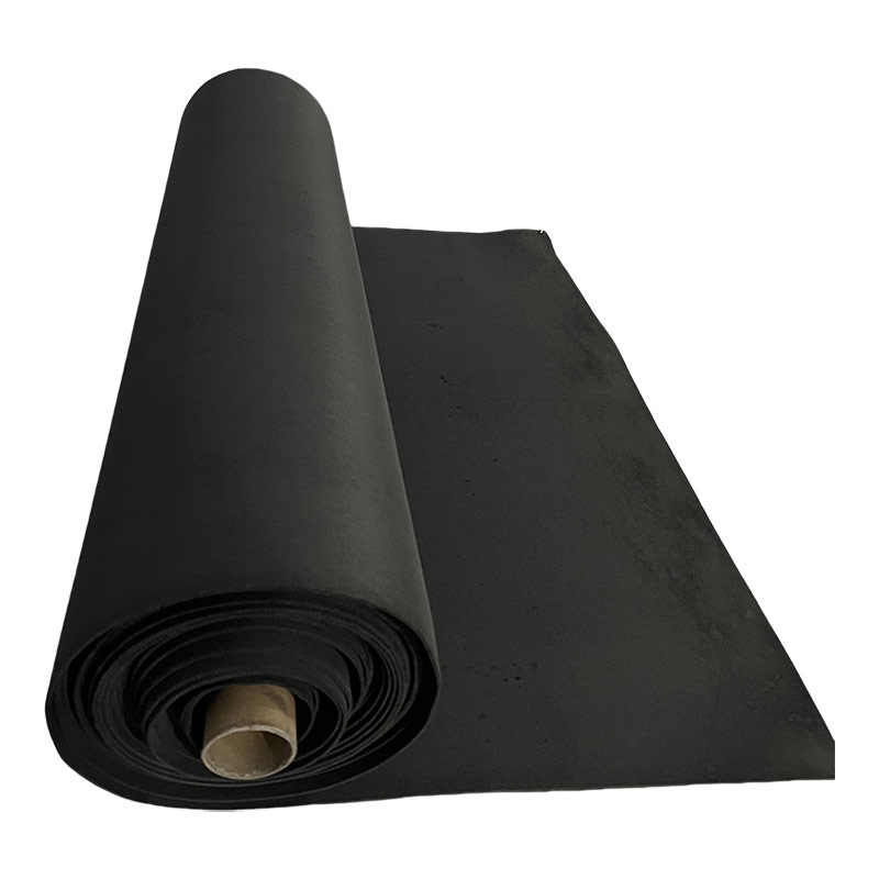
Felt is the workhorse electrode for VRFB and zinc-bromine systems. PAN-based carbon felt, carbonized near 1000 to 1500 C, is the cost-effective default. Graphite felt, heat treated above 2000 C, delivers higher conductivity and stronger corrosion resistance. Viscose-based graphite felt adds a more uniform pore structure, which helps control zinc deposition in zinc-bromine cells. Typical specifications are 3 to 6 mm thickness, 85 to 95% porosity, and 20 to 30% compressibility under stack clamping.
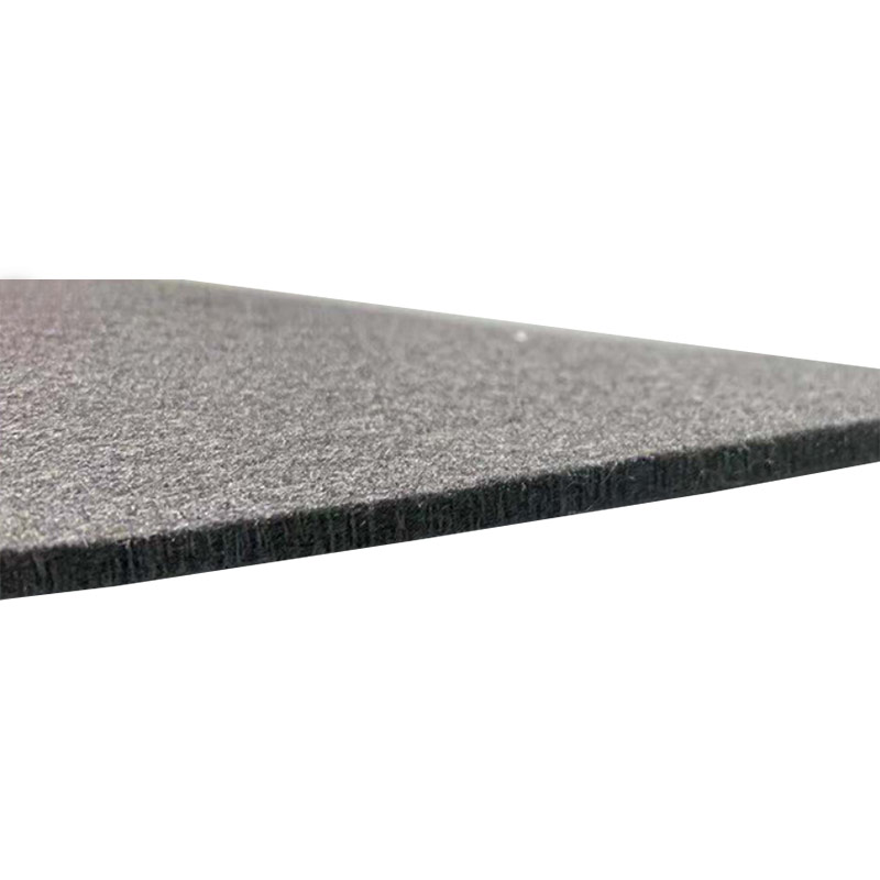 Gas-Phase Deposited Electrode Felt for Flow BatteriesThis electrode felt uses a CVD process to grow carbon nanotubes on carbon fibers, achieving high specific surface area and permanent hydrophilicity. It also incorporates pyrrole and pyridine structures to suppress hydrogen evolution, making it suitable for various flow battery electrode applications.View Product →
Carbon and graphite cloths
Cloth electrodes range from 0.2 to 1.0 mm thick and provide higher in-plane conductivity and lower hydraulic resistance than felt. They fit zero-gap cell designs and flow batteries with limited pump pressure budgets. Because the weave creates periodic contact points, clamping pressure distribution matters more than with felt.
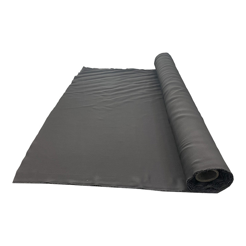
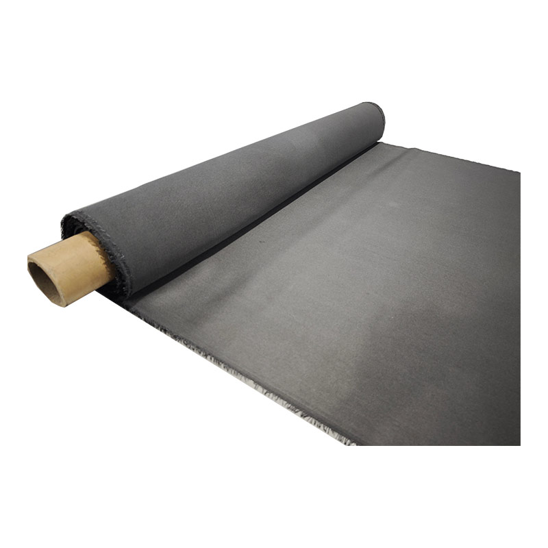 CVD-Treated Electrode Cloth with Tailored WettabilityThis electrode cloth is produced via gas-phase deposition, featuring carbon nanotubes for enhanced surface area and either permanent hydrophilicity or hydrophobicity depending on the variant. It suits electrolytic cells and fuel cells, with customizable textile specifications for different cell designs.View Product →
Bipolar plates and flow channel plates
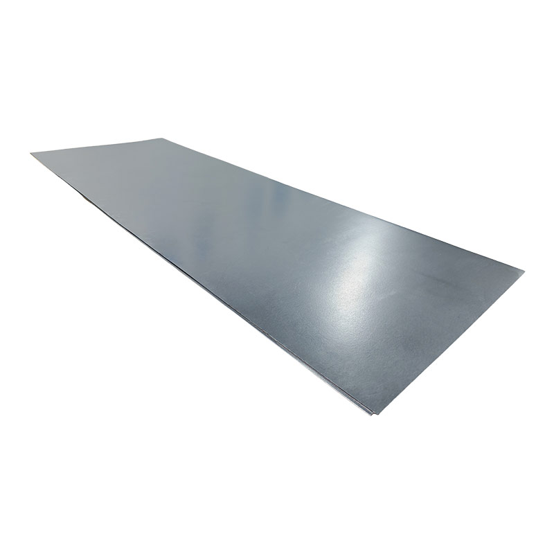
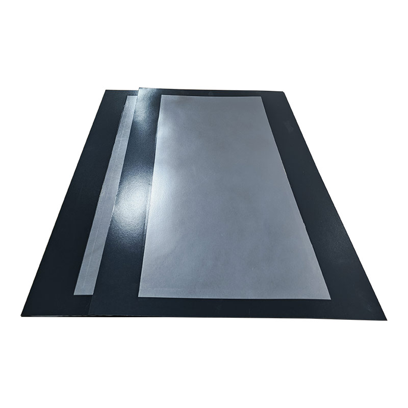
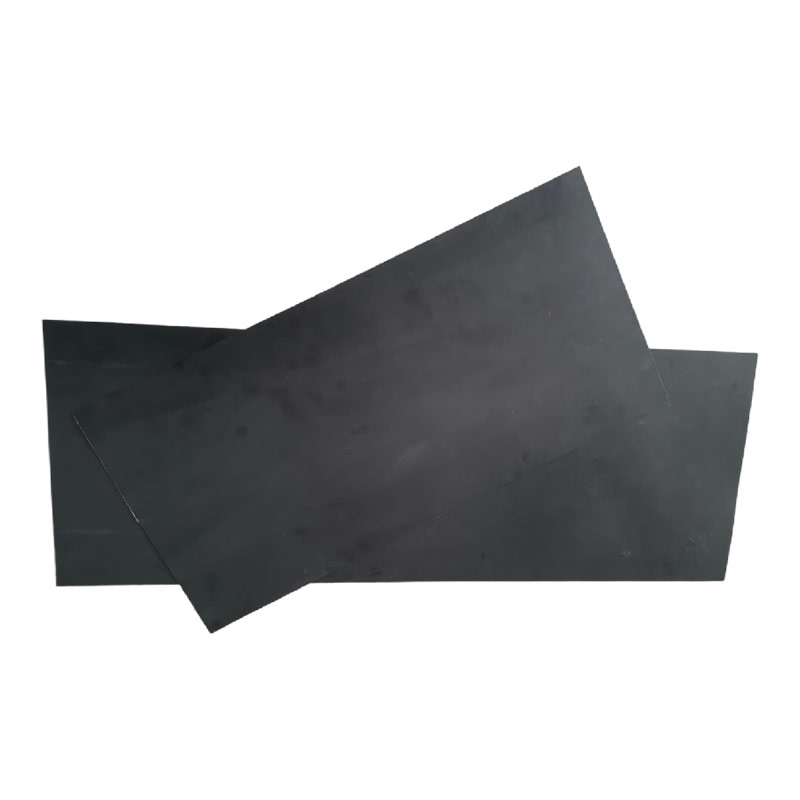
Bipolar plates separate adjacent cells while carrying current across the stack. A carbon bipolar plate must be liquid and gas impermeable, chemically inert in hot acidic electrolyte, and conductive both in-plane and through thickness. Flexible graphite composite plates can be stamped with flow fields; carbon fiber reinforced plates add stiffness and creep resistance, which keeps clamping force stable over thousands of cycles. Flow channel plates distribute electrolyte evenly and are offered in both flexible and rigid grades.
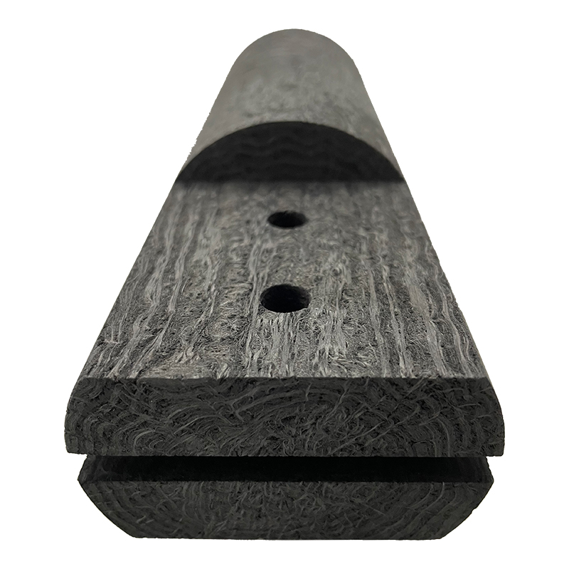
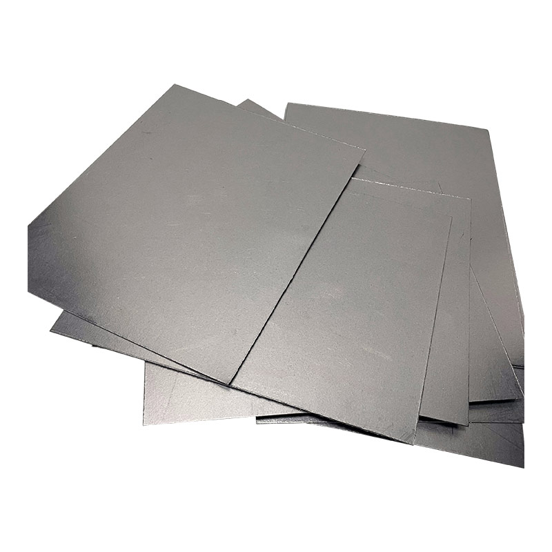 Carbon Fiber Reinforced Flexible Graphite Bipolar PlateThis bipolar plate combines high electrical conductivity with exceptional flexibility, bending 360 degrees without breaking, and offers strong compressive and flexural strength. Its low hydrogen permeability at operational pressure makes it a robust choice for flow battery stacks requiring durable, leak-resistant separation.View Product →
When you review supplier data, ask for in-plane conductivity, through-plane resistance, flexural strength, impermeability test method, thickness tolerance, and a compression deflection curve.
The right electrode material keeps ohmic drop and activation overpotential in balance at your target current density without starving the flow field.
How Electrode Material Properties Map to Battery Metrics
The relationship is direct: higher through-plane conductivity raises voltage efficiency, more oxygen functional groups speed up the redox reaction, and wider pores lower pumping loss at the cost of reaction surface area.
The chart below places the main carbon electrode material families on a logarithmic in-plane conductivity scale. The bands are typical supplier ranges, not absolute limits.
Electrode felt quality directly changes zinc-bromine cell stability and efficiency, as Naco explains in its analysis of electrode felt quality. The same material principle applies to VRFB stacks.
| Material | Typical thickness | Porosity | Main trade-off | Stack role |
| PAN-based carbon felt | 3 to 6 mm | 88 to 95% | Low cost vs moderate conductivity | Default VRFB electrode |
| PAN-based graphite felt | 3 to 6 mm | 85 to 93% | Higher conductivity vs price | High-efficiency VRFB cells |
| Carbon or graphite cloth | 0.2 to 1.0 mm | 70 to 85% | Low pressure drop vs less active area | Zero-gap and thin electrodes |
| Composite flexible graphite bipolar plate | 2 to 5 mm | Sealed | Formability vs creep resistance | Cell separation and current collection |
2000 C
Graphitization temperature for high-conductivity felt
20-30%
Compression of felt in a clamped stack
2 to 3x
Charge transfer resistance reduction from surface treatment
Surface Chemistry Matters More Than Bulk Conductivity
Bulk conductivity gets current to the reaction site; surface chemistry decides whether the reaction runs fast enough to use it. In carbon electrode materials, the two must be developed together.
The VO2+/VO2+ couple on the positive side of a VRFB is sluggish on pristine graphite. Thermal oxidation in air at 400 to 500 C, or acid treatment, introduces hydroxyl, carboxyl, and carbonyl groups that act as catalytic sites. These treatments routinely reduce charge transfer resistance by 2 to 3 times, and the benefit can be lost if the material is improperly stored or handled.
Untreated Carbon Felt
- Lower surface oxygen content
- Higher charge transfer resistance
- Usually cheaper
- Acceptable for low-rate tests only
Surface-Treated Carbon Felt
- Oxygen functional groups on fibers
- Lower activation overpotential
- Slightly higher material cost
- Needed for rated power operation
Stack designers should request surface characterization, not just conductivity values. Cyclic voltammetry curves, XPS survey spectra, and contact angle measurements tell you whether the surface was actually activated. Suppliers with controlled post-treatment lines, such as Naco's electrode surface chemistry work for VRFB power density, produce more consistent cell results.
An electrode with excellent bulk conductivity but an untreated surface will underperform a properly activated material in a flow battery.
A Practical Framework for Specifying Electrode Materials
Four checks narrow a long list of electrode materials to a test-worthy shortlist: operating envelope, electrochemical evidence, mechanical behavior under compression, and supplier process control.
- Fix the operating envelope. Define current density, flow rate, temperature, and electrolyte chemistry before comparing any materials. A 100 mA/cm2 design target demands a different felt than a 40 mA/cm2 design.
- Demand electrochemical evidence. Ask for half-cell polarization data, charge transfer resistance, and cycling results at your state-of-charge window, not just a single conductivity number.
- Evaluate mechanical behavior under stack compression. Measure thickness loss, flow channel intrusion, and creep after extended cycling, because a felt that relaxes changes the hydraulic balance of the stack.
- Audit supplier process control. Check precursor traceability, graphitization records, defect inspection methods, and lot-to-lot thickness and porosity data.
When you source electrode materials from a custom conductive carbon factory, you can adjust fiber diameter, porosity, thickness, and edge treatment to your stack design. A trading intermediary can only resell what someone else decided to make.
Frequently Asked Questions about Electrode Materials
Short, direct answers to the questions stack designers ask most during electrode material selection.
What is the difference between carbon felt and graphite felt?
Carbon felt is carbonized at roughly 1000 to 1500 C and offers moderate conductivity at lower cost. Graphite felt is heat treated above 2000 C, which raises electrical conductivity, thermal stability, and corrosion resistance. For long-life flow batteries operating in acidic electrolytes, graphite felt is usually the safer choice.
How thick should a flow battery electrode be?
Most VRFB stacks use felt electrodes from 3 to 6 mm uncompressed, compressed by 20 to 30% during assembly. Thinner cloth electrodes from 0.2 to 1.0 mm suit zero-gap designs where pumping loss and internal resistance must be minimized. Thickness is always a compromise between reaction area and flow resistance.
Why does electrode surface treatment matter?
The redox reactions in vanadium and zinc-bromine systems are slow on pristine carbon. Surface oxidation creates oxygen functional groups that accelerate the reaction, typically reducing charge transfer resistance by 2 to 3 times. Without treatment, even a highly conductive felt delivers disappointing voltage efficiency.
Can the same electrode material serve vanadium and zinc-bromine batteries?
Not without care. VRFB applications emphasize conductivity, corrosion resistance, and surface activity, while zinc-bromine cells need a uniform pore structure to control zinc deposition. Viscose-based graphite felt with a tight pore-size distribution is often preferred for zinc-bromine; PAN-based graphite felt is the common VRFB default.
The single most useful habit: test the electrode in your electrolyte, not on a datasheet.